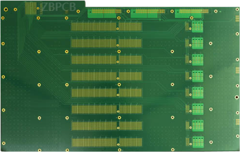
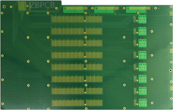
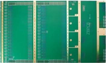
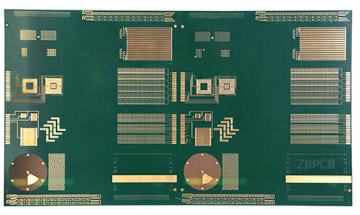
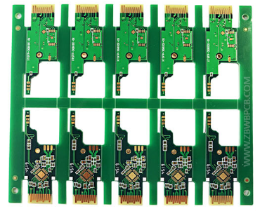
High speed PCB
Model: high speed PCB
Layer: 8 Layer PCB
Material: Panasonic M6 high speed PCB
Finished Thickness:1.0mm
Copper Thickness: 0.502/10Z
Color: Green/white
Surface treatment: Electric hard gold
Special technology: golden fnger bevel
Min Trace / Space: 3mil/3mil
Application: Optical Module high speed PCB
What is high speed PCB?
High-speed PCB uses such a circuit board. When the frequency of the digital logic circuit reaches or exceeds 45MH2~50MH2, it is called a high-speed circuit. The circuit working at this frequency
has accounted for one-third of the entire electronic system.
How to choose PCB materials for high-speed design?
The requirements for high-speed PCB materials are as follows:
1. Low loss, good CAF/heat resistance, strong mechanical toughness (good adhesion) (good reliability)
2. Stable Dk/DF parameters (small coefficient of variation with frequency and environment)
3. Small tolerance of material thickness and glue content (good impedance control)
4. Low surface roughness of copper foil (reduce loss)
5. Try to choose glass fiber cloth with flat windows (reduce deflection and loss)
The integrity of high-speed signals is mainly related to impedance consistency, transmission line loss, delay, etc.
The ability to receive appropriate waveforms and eye diagrams at the receiving end can be considered to ensure the integrity of the signal.
Therefore, the main parameter indicator for selecting high-speed PCB materials is kDE loss. Whether it is a common circuit or an industrial circuit,
The dielectric constant DK of high-speed PCB materials is an important parameter for material selection.
Because the DK value is closely related to the circuit impedance value actually applied to the material, when the DK value of the high-speed PCB material changes,
The transmission impedance of the circuit will change unpredictably, whether it changes with frequency or temperature.
If the DK value of the PCB material presents different values for harmonic components of different frequencies, its impedance also has different resistance values at different frequencies.
The unexpected changes in the DK value and impedance will cause certain losses and frequency errors to several harmonic components, distorting the analog harmonic components of high-speed digital signals,
Thereby reducing the stability of the signal. Dispersion related to the DK value is also a characteristic of high-speed PCB materials.
The smaller the change of the DK value with frequency, the smaller the dispersion, and the better the reliability of high-speed digital circuits.
The polarization of dielectric materials, the loss of high-speed PCB materials, and the roughness of the surface of high-frequency copper conductors will all cause dispersion in the circuit.
Therefore, the dielectric constant D value of high-speed materials is required to be stable. The smaller the fluctuation of dielectric constant in different frequency bands and temperatures,
The better the performance.
High-speed PCB transmission line loss usually includes dielectric loss, conductor loss and radiation loss. Dielectric loss is also called insulation loss.
The insulation loss of high-speed PCB signals increases with the increase of frequency, especially with the change of high-order harmonic components of high-speed signals.
Dielectric loss is proportional to frequency, the square root of dielectric constant DK of insulation layer and dielectric loss factor DF of insulation layer, and is related to the type of conductor.
Different dielectric constants DK have different resistivity. In fact, the size and physical size of conductors are also different, which is proportional to the source of dielectric loss.
In high-speed PCB manufacturing, the effect of using different substrates on conductor loss is mainly caused by skin effect and surface roughness.
When using different copper foils, the surface roughness of the insulation layer is different.
Affected by the depth of skin effect, the copper tooth length of copper foil will directly affect the transmission quality of high-speed signals.
The shorter the length of the copper teeth, the better the transmission quality of high-speed signals.
The radiation loss PcB of high-speed cables is related to the dielectric properties and is proportional to the dielectric constant DK, dielectric loss factor DF and the square root of the frequency.

What are the materials used for your high-speed PCB?
The usual answer is FR4. The PB board we are talking about usually refers to the substrate,
Which is actually composed of copper foil and prepreg, and copper foil and prepreg have many classifications according to different uses.
FR4 uses epoxy resin or modified epoxy resin as an adhesive and glass fiber as a molding material. In other words,
As long as the material of this system is used, it can be called FR4, so FR4 is a general term for this resin system.
Printed boards using FR4 materials are currently the largest and most used type of printed boards in the world.
Generally speaking, FR4 is classified according to the following types.
1. According to the naming classification of glass fiber cloth weaving, such as. 106, 1067, 1080, 1078, 2116, 2113, 3313, 7628, etc.
The above are the commonly used glass fiber cloth models, of course, there are others, each type of glass fiber cloth is defined in the lpc specification,
So the same glass fiber cloth used by different pcb manufacturers will not be much different, because there are also many pcb manufacturers of glass fiber cloth,
But the same glass fiber cloth provided by different pcb manufacturers must meet the requirements of the zbpcb specification.
2. Classification by glass type E-glas: E stands for Electrica, that is, insulating glass, which is a calcium aluminate glass with an alkali metal oxide content generally less than 196%,
So it is also called alkali-free glass with a higher resistivity. E-glas has now become the most commonly used glass fiber component,
And many pcb materials usually use E-glas instead of other designated NE glass (INE-glas). Also known as Low-Dk glass, it is a dielectric fiber glass developed by Japan Ritsuto Textile Co., Ltd.
Its dielectric constant 1MH2 is 4.6, and Eglas is 6.6. The Thelos factor Thetan8 (1MHz) is 0.0007 (E glass is 0.0012). Commonly used NE glass materials include M7NE, IT968SE, IT988GSE, etc.
3. According to the resin syshem used by the Pc8 supplie and its perfommance dassificatio
Iteg high-speed PCB materials:
IT180AT170GRA1MT95GMT968TT968SETT988GSE
Tuc high-speed PCB materials:
Tu862H57u872LTuB725LK7u8725LK-5PTu883u933+
Panasonic high-speed PCB materials:
Megton4M4SMegtrn6M6GM7EM7NE
Park Meteorwave series:
MVV100CV2000V3000/40009000ShengYi high-speed PCB materials: 51000-2(MV5743956,
2c.Rogers high-speed PCB materials: R04003R03003,R04
3.508|RF materials, etc.
4.classifcabon sccorcing to the loss leveIt can be dividled into ordinary lass sheet (0f20.02y, medium loss sheet 10.01
5. According to the classification of flame retardant properties, carbon has flame retardant type (UL94-V, UL94-Vly) and non-flame retardant type (ILG4-HB grade). After reading the above introduction, back to the previous question, what kind of high-speed board do we usually use? Of course, it should be selected according to the material name and the resin system and performance used by the board supplier, such as! T180AS100-20T96BM4s, etc. According to different models and materials of different mainstream manufacturers, it is mainly based on automotive and high-speed cables, and its loss is lower than that of ordinary F4, while some FR4, such as: 1T190A, S10-2M, Tu752768, etc. are basically the same as it. Ta refers to Meaton6/M6G for high-speed PCB.
High-speed pcB design, high-speed PtB principle To design a high-precision high-speed PCE, we must not only consider signal linearity and power input,
But also understand the difference between high-speed signals and high-performance signals, and understand the difference between high-speed signals and high-performance signals in PCE design.
Although these eating habits form a structure, we still need to reconsider the signal integrity design of the final high-speed PCB. Due to the high power density, when designing and building,
The transmission density problem and the specifications that must be met when transmitting and receiving sound and providing specific functions must be considered. In addition,
Some design challenges need to be addressed, such as high-speed transmission integrity, thermal management, and how to prevent electromagnetic interference between data and circuit boards.
Higher frequencies require the use of appropriate tools in circuit boards to capture and transmit low and high signals without signal and electromagnetic interference. In order to make devices lighter, smaller,
And more portable, circuit board materials must be flexible and lightweight to accommodate all microelectronic devices on the circuit board.
In order to carry out thin-layer wiring, wiring and strict control must be considered, and the subtractive etching process required for 3 and 4G high-speed Pgs will be the key in the future.
Switching to a semi-additive process,
These improved semi-additive processes will provide more precise routing and strength and are ideal as the d and e of the slow speed PCB are 35 to 55 of the d and e of the slow speed PCaae.
It is a braided water pipe, loss msteisd and kw gfe soppe, will slow the d and e of the slow speed PCaae,
And sto create inalbss animmorve signal integrity crcsstalkc and perastc capsatance is a major issue in circuit engineering.
To avoid crosstalk and ewl caused by analog and digital frequencies on the board, separate routing is highly recommended.
Using multiple boards will provide better flexibility in determining how to do high speed routing so that the analog and digital return signals are routed away from each other while keeping the
AC side circuits separated. Adding shielding and filters when laying out components should also reduce the current of natural electromagnetic fields on the PCB.
To ensure that there are no defects and serious short circuits or copper surface peeling,
The advanced automatic visual inspection system (Aj0y with other functions and 2D technology) will help circuit board engineers lock in possible failure risks.
Metrology will be used to check the wiring of the wires will affect the conductive properties of the PcB.
The dielectric material and the PCe material of the core substrate layer need to fully handle the high spectrum, because these problems will cause the degradation of Pa3.
Therefore, Techneno mae to discuss these major issues, which include thermal conductivity and thermal coefficient. Materials with high conductivity
High-speed Pig design is to connect multiple Pigs to each other. In the channel where multiple devices are closely arranged, various factors must be considered during design and a comprehensive compromise must be made, so that the design requirements can be met and the design speed can be reduced. The reliability of the Pig is the controllability of the design process. Only with good controllability can the high-speed Pig design be reliable and successful.
High-speed Pc8, also known as high-speed PcB board or high-speed Pc8 board, is a high-speed PC board manufactured with high-speed CB board, which has the characteristics of fast speed, high performance, Low power consumption and high bandwidth. High-speed PcB is widely used in 5G communication field, such as 5G base stations and mobile computers. High-speed Pc board is also an important part of 5G Product line. Pc can provide users with the following services: sosdPs design dedicated Pcs samples, sced Pcs manufacturing dedicated Pcs, sMT olNoh-sctd PcE, amdPcs service. Foney hip replacement